This is a post I have been meaning to do for some time now but just never got around to it. Let me first start off by saying that there are a ton of resources on the web about this particular collision detection algorithm. The problem I had with the available resources is that they are often vague when explaining some of the implementation details (probably for our benefit).
I plan to explain the algorithm and also fill in some of the blanks that I had when implementing this myself.
First let me start off by saying there is a great tutorial with interactive flash examples.
- Introduction
- Convexity
- Projection
- Algorithm
- Obtaining The Separating Axes
- Projecting A Shape Onto An Axis
- Finding the MTV
- Curved Shapes
- Containment
- Other Things To Note
Introduction
The Separating Axis Theorem, SAT for short, is a method to determine if two convex shapes are intersecting. The algorithm can also be used to find the minimum penetration vector which is useful for physics simulation and a number of other applications. SAT is a fast generic algorithm that can remove the need to have collision detection code for each shape type pair thereby reducing code and maintenance.
Convexity
SAT, as stated before, is a method to determine if two convex shapes are intersecting. A shape is considered convex if, for any line drawn through the shape, that line crosses only twice. If a line can be drawn through the shape and cross more than twice the shape is non-convex (or concave). See and for more mathematical and formal definitions. So lets look at some examples:
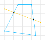
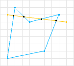
The first shape is considered convex because there does not exist a line that can be drawn through the shape where it will cross more than twice. The second shape is not convex because there does exists a line that crosses more than twice.
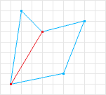
SAT can only handle convex shapes, but this is OK because non-convex shapes can be represented by a combination of convex shapes (called a convex decomposition). So if we take the non-convex shape in figure 2 and perform a convex decomposition we can obtain two convex shapes. We can then test each convex shape to determine collision for the whole shape.
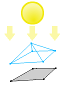
(or shadow)
Projection
The next concept that SAT uses is projection. Imagine that you have a light source whose rays are all parallel. If you shine that light at an object it will create a shadow on a surface. A shadow is a two dimensional projection of a three dimensional object. The projection of a two dimensional object is a one dimensional “shadow”.
Algorithm
SAT states that: “If two convex objects are not penetrating, there exists an axis for which the projection of the objects will not overlap.”
No Intersection
First lets discuss how SAT determines two shapes are not intersecting. In figure 5 we know that the two shapes are not intersecting. A line is drawn between them to illustrate this.
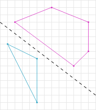
If we choose the perpendicular line to the line separating the two shapes in figure 5, and project the shapes onto that line we can see that there is no overlap in their projections. A line where the projections (shadows) of the shapes do not overlap is called a separation axis. In figure 6 the dark grey line is a separation axis and the respective colored lines are the projections of the shapes onto the separation axis. Notice in figure 6 the projections are not overlapping, therefore according to SAT the shapes are not intersecting.

Their Respective Projections
SAT may test many axes for overlap, however, the first axis where the projections are not overlapping, the algorithm can immediately exit determining that the shapes are not intersecting. Because of this early exit, SAT is ideal for applications that have many objects but few collisions (games, simulations, etc).
To explain a little further, examine the following psuedo code.
Axis[] axes = // get the axes to test;
// loop over the axes
for (int i = 0; i < axes.length; i++) {
  Axis axis = axes[i];
  // project both shapes onto the axis
  Projection p1 = shape1.project(axis);
  Projection p2 = shape2.project(axis);
  // do the projections overlap?
  if (!p1.overlap(p2)) {
    // then we can guarantee that the shapes do not overlap
    return false;
  }
}

Intersection
If, for all axes, the shape’s projections overlap, then we can conclude that the shapes are intersecting. Figure 7 illustrates two convex shapes being tested on a number of axes. The projections of the shapes onto those axes all overlap, therefore we can conclude that the shapes are intersecting.
All axes must be tested for overlap to determine intersection. The modified code from above is:
Axis[] axes = // get the axes to test;
// loop over the axes
for (int i = 0; i < axes.length; i++) {
  Axis axis = axes[i];
  // project both shapes onto the axis
  Projection p1 = shape1.project(axis);
  Projection p2 = shape2.project(axis);
  // do the projections overlap?
  if (!p1.overlap(p2)) {
    // then we can guarantee that the shapes do not overlap
    return false;
  }
}
// if we get here then we know that every axis had overlap on it
// so we can guarantee an intersection
return true;
Normals
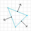
The first question I had when implementing this algorithm was how do I know what axes to test? This actually turned out to be pretty simple:
The axes you must test are the normals of each shape’s edges.
The normals of the edges can be obtained by taking the perproduct of the edge vector. For example:
Vector[] axes = new Vector[shape.vertices.length];
// loop over the vertices
for (int i = 0; i < shape.vertices.length; i++) {
  // get the current vertex
  Vector p1 = shape.vertices[i];
  // get the next vertex
  Vector p2 = shape.vertices[i + 1 == shape.vertices.length ? 0 : i + 1];
  // subtract the two to get the edge vector
  Vector edge = p1.subtract(p2);
  // perform the perproduct to obtain the normal
  Vector normal = edge.perp();
  // the perp method is just (x, y) => (-y, x) or (y, -x)
}
Perform this for each shape to obtain two lists of axes to test. Doing this changes the pseudo code from above to:
Axis[] axes1 = shape1.getAxes();
Axis[] axes2 = shape2.getAxes();
// loop over the axes1
for (int i = 0; i < axes1.length; i++) {
  Axis axis = axes1[i];
  // project both shapes onto the axis
  Projection p1 = shape1.project(axis);
  Projection p2 = shape2.project(axis);
  // do the projections overlap?
  if (!p1.overlap(p2)) {
    // then we can guarantee that the shapes do not overlap
    return false;
  }
}
// loop over the axes2
for (int i = 0; i < axes2.length; i++) {
  Axis axis = axes2[i];
  // project both shapes onto the axis
  Projection p1 = shape1.project(axis);
  Projection p2 = shape2.project(axis);
  // do the projections overlap?
  if (!p1.overlap(p2)) {
    // then we can guarantee that the shapes do not overlap
    return false;
  }
}
// if we get here then we know that every axis had overlap on it
// so we can guarantee an intersection
return true;
Projecting A Shape Onto An Axis
Another thing that wasn’t clear was how to project a shape onto an axis. To project a polygon onto an axis is relatively simple; loop over all the vertices performing the dot product with the axis and storing the minimum and maximum.
double min = // really small number;
double max = // really large number;
for (int i = 0; i < shape.vertices.length; i++) {
  // NOTE: the axis must be normalized to get accurate projections
  double p = axis.dot(shape.vertices[i]);
  if (p < min) {
    min = p;
  } else if (p > max) {
    max = p;
  }
}
Projection proj = new Projection(min, max);
return proj;
Finding the MTV
So far we have only been returning true or false if the two shapes are intersecting. In addition to thi,s SAT can return a Minimum Translation Vector (MTV). The MTV is the minimum magnitude vector used to push the shapes out of the collision. If we refer back to figure 7 we can see that axis C has the smallest overlap. That axis and that overlap is the MTV, the axis being the vector portion, and the overlap being the magnitude portion.
To determine if the shapes are intersecting we must loop over all the axes from both shapes, so at the same time we can keep track of the minimum overlap and axis. If we modify our pseudo code from above to include this we can return a MTV when the shapes intersect.
double overlap = // really large value;
Axis smallest = null;
Axis[] axes1 = shape1.getAxes();
Axis[] axes2 = shape2.getAxes();
// loop over the axes1
for (int i = 0; i < axes1.length; i++) {
  Axis axis = axes1[i];
  // project both shapes onto the axis
  Projection p1 = shape1.project(axis);
  Projection p2 = shape2.project(axis);
  // do the projections overlap?
  if (!p1.overlap(p2)) {
    // then we can guarantee that the shapes do not overlap
    return false;
  } else {
    // get the overlap
    double o = p1.getOverlap(p2);
    // check for minimum
    if (o < overlap) {
      // then set this one as the smallest
      overlap = o;
      smallest = axis;
    }
  }
}
// loop over the axes2
for (int i = 0; i < axes2.length; i++) {
  Axis axis = axes2[i];
  // project both shapes onto the axis
  Projection p1 = shape1.project(axis);
  Projection p2 = shape2.project(axis);
  // do the projections overlap?
  if (!p1.overlap(p2)) {
    // then we can guarantee that the shapes do not overlap
    return false;
  } else {
    // get the overlap
    double o = p1.getOverlap(p2);
    // check for minimum
    if (o < overlap) {
      // then set this one as the smallest
      overlap = o;
      smallest = axis;
    }
  }
}
MTV mtv = new MTV(smallest, overlap);
// if we get here then we know that every axis had overlap on it
// so we can guarantee an intersection
return mtv;
Curved Shapes
We have seen how polygons can be tested using SAT, but what about curved shapes like a circle? Curved shapes pose a problem for SAT because curved shapes have an infinite number of separating axes to test. The way this problem is usually solved is by breaking up the Circle vs Circle and Circle vs Polygon tests and doing some more specific work. Another alternative is to not use curved shapes at all and replace them with high vertex count polygons. The second alternative requires no change to the above pseudo code, however I do want to cover the first option.
Let’s first look at Circle vs Circle. Normally you would do something like the following:
Vector c1 = circle1.getCenter();
Vector c2 = circle2.getCenter();
Vector v = c1.subtract(c2);
if (v.getMagnitude() < circle1.getRadius() + circle2.getRadius()) {
  // then there is an intersection
}
// else there isnt
We know two circles are colliding if the centers are closer than the sum of the circle’s radii. This test is actually a SAT like test. To achive this in SAT we could do the following:
if (shape1.isCircle() &amp;amp;amp;amp;&amp;amp;amp;amp; shape2.isCircle()) {
Vector[] axes = new Vector[1];
// for two circles there is only one axis test
axes[0] = shape1.getCenter().subtract(shape2.getCenter);
}
// then all the SAT code from above
Circle vs Polygon poses more of a problem. The center to center test along with the polygon axes is not enough (In fact the center to center test can be omitted). For this case you must include another axis: the axis from the closest vertex on the polygon to the circle’s center. The closest vertex on the polygon can be found in a number of ways, the accepted solution using Voronoi regions which I will not discuss in this post.
Other curved shapes are going to be even more of a problem and must be handled in their own way. For instance a capsule shape could be decomposed into a rectangle and two circles.
Containment
One of the problems that many developers choose to ignore is containment. What happens when a shape contains another shape? This problem is usually not a big deal since most applications will never have this situation happen. First let me explain the problem and how it can be handled. Then I’ll explain why it should be considered.
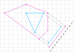
If one shape is contained in another shape SAT, given the pseudo code we have so far, will return an incorrect MTV. Both the vector and magnitude portions may not be correct. Figure 9 shows that the overlap returned is not enough to move the shapes out of intersection. So what we need to do is check for containment in the overlap test. Taking just the if statement from the above SAT code:
if (!p1.overlap(p2)) {
  // then we can guarantee that the shapes do not overlap
  return false;
} else {
  // get the overlap
  double o = p1.getOverlap(p2);
  // check for containment
  if (p1.contains(p2) || p2.contains(p1)) {
    // get the overlap plus the distance from the minimum end points
    double mins = abs(p1.min - p2.min);
    double maxs = abs(p1.max - p2.max);
    // NOTE: depending on which is smaller you may need to
    // negate the separating axis!!
    if (mins < maxs) {
      o += mins;
    } else {
      o += maxs;
    }
  }
  // check for minimum
  if (o < overlap) {
    // then set this one as the smallest
    overlap = o;
    smallest = axis;
  }
}
Reason #1: It IS possible that the shapes could get in this type of configuration. Not handling this would require two or more iterations of SAT to resolve the collision depending on the relative sizes of the shapes.
Reason #2: If you plan to support Line Segment vs. Other shapes you have to do this because the overlap can be zero in some cases (this is due to the fact that a Line Segment is an infinitely thin shape).
Other Things To Note
Some other things to note:
- The number of axes to test can be reduced by not testing parallel axes. This is why a rectangle only has two axes to test.
- Some shapes like a rectangle can perform faster if it has its own projection and getAxes code since a rectangle doesn’t need to test 4 axes but really just 2.
- The last separation axis could be used to prime the next iteration of SAT so that the algorithm could be O(1) in non-intersection cases.
- SAT in 3D can end up testing LOTS of axes.
- I’m not an expert and please excuse my terrible graphics.
Hi I am very interested in your post on SAT. I found the post to be very clear and informing as I am currently trying to implement a SAT based collision test between a rectangle and a circle. My question has to do with projecting a shape on an axis, you made a note in your pseudo code that the axis should be normalized. How would you achive this?
In my case I am finding the axis that I want to project onto by taking the vector between the rectangles closest corner and the circles center (I only do this if the circles center is not directly over or next to the rectangle). This vector should define the axis that I want to project onto but how do I Normalize this? Am I just over complicating the issue, and should I normalize the vector by making it a unit vector?
Cheers Greg
No, you are on the right track. Normalization is the same thing as making it a unit vector:
Say your axis is the vector (3, 4) to normalize (i.e. make it a unit vector) just find the length:
l = sqrt(x2 + y2)
l = sqrt( 3 * 3 + 4 * 4 ) = 5
Then divide by the length
= (3/5, 4/5) = (0.6, 0.8)
“The closest vertex on the polygon can be found in a number of ways, the accepted solution using Voronoi regions which I will not discuss in this post.”
doh!!!
who can help me about using voronoi to find the closest vertex? :(
Checking what voronoi region a point lies in can be performed by a number of side of line tests. For instance the GJK algorithm uses this to determine where the origin is relative to the simplex. See my GJK post to get an idea.
It may not even be worth it if your polygons have a small number of vertices, especially in 2D. In fact, in my dyn4j project I use the brute force method and it never shows up on the profiler (mostly because you don’t compare the distance, but instead the squared distance). This is only 5 operations per vertex (2 subtraction, 2 multiplication, and one addition). It would be difficult to beat this in the general case.
First of all I would like to thank you for this tutorial. It is far clearer than many others that I have encountered online.
I was implementing separating axis, using this guide, and was curious about the implementation of Projection. Is the following how you would implement it? I am particularly concerned about getOverlap.
public class Projection { private final float m_min; private final float m_max; public Projection(float min, float max) { m_min = min; m_max = max; } public boolean doesOverlap(final Projection other) { if(m_max > other.m_min) { return true; } if(m_min > other.m_max) { return true; } return false; } public double getOverlap(final Projection other) { if(!doesOverlap(other)) { return 0; } if(m_max > other.m_min) { return Collider.getDistance(m_max, other.m_min); } else if(m_min > other.m_max) { return Collider.getDistance(m_min, other.m_max); } else { Log.warning("Bad case in getOverlap!"); return 0; } } }Sorry I was away for a while and just now catching up. You can look at the implementation of the class as an example.
But if you are anything like me you like to figure things out on your own. Here is what I would suggest, write down some examples for the different cases:
(0, 4) and (2, 6) normal case
(0, 3) and (4, 7) no overlap
(3, 6) and (0, 2) no overlap, reversed
(0, 3) and (3, 6) no overlap, “touching”
(0, 7) and (1, 4) overlap, containment
(0, 2) and (0, 2) same projection
etc.
and try out your methods.
For example, the method doesOverlap has some problems with example #3 that I have given since the first condition is true, yet the projections do not overlap.
As for the getOverlap method I can’t really say since I’m not sure what Collider.getDistance is doing, but I’ll try to answer. After the check to make sure the two projections overlap you only need to subtract two of the values:
For example if the projections are:
(0, 3) and (2, 30) then we only need to perform 3 – 2
Lets look at another case:
(4, 20) and (-1, 7) then we only need to perform 7 – 4
Lets look at another case:
(1, 10) and (2, 4) then we only need to perform 4 – 2
And another case:
(0, 3) and (3, 5) then we only need to perform 3 – 3
Lets look at one more case and you may see a pattern:
(-2, 6) and (-1, 10) then we only need to perform 6 – -1
I’ll drop in a hint, it involves using max and min.
Thanks for the compliment btw,
William
Thanks — nice, informative post.
I looked at your question you posted there and the answer given is pretty much correct.
However, to be safe its good to make sure you use the correct one, which depends on the winding of the polygon. If the winding of the polygon is Counter-Clockwise then you should use the normal that points right of the edge. If the polygon winding is clockwise, you should use the normal that points left of the edge. (This is why many engines require a winding direction of CCW or CW)
Referring to the really bad image above, and just using the edge (1, 1) to (2, 1.5) we get:
If we used used the left hand normal for this edge we would get a normal that points in instead of out of the polygon. If we reverse the winding:
As we can see we would want to use the left normal in this case.