Today I’m going to talk about the other collision detection algorithm packaged with the dyn4j project. You can find a lot of GJK documentation but much of it is really technical mostly because they are research papers. I strongly recommend this and to be honest you may not even need to read any further after watching. But if you feel you need more information after watching the video please read on.
- Introduction
- Convexity
- Minkowski Sum
- The Simplex
- The Support Function
- Creating The Simplex
- Determining Collision
- Iteration
- Checking The Simplex
Introduction
GJK, like SAT, only operates on convex shapes. One of the more attractive features of GJK is that it can support any shape that implements a “support function” (we’ll talk about this later). Therefore, unlike SAT, you don’t need to handle curved shapes, for example, using special code or algorithms.
GJK is an iterative method but converges very fast and if primed with the last penetration/separation vector can run in near constant time. It’s a better alternative to SAT for 3D environments because of the number of axes that SAT must test.
GJK’s original intent was to determine the distance between two convex shapes. GJK can also be used to return collision information for small penetrations and can be supplemented by other algorithms for deeper penetrations.
Convexity
As I said earlier, GJK is an algorithm that can only be used with convex shapes. See my post on SAT for an explaination of convexity.
Minkowski Sum
The GJK algorithm relies heavily on a concept called the Minkowski Sum. The Minkowski Sum conceptually is very easy to understand. Let’s say you have two shapes, the Minkowski Sum of those shapes is all the points in shape1 added to all the points in shape2:
A + B = {a + b|a∈A, b∈B}
If both shapes are convex, the resulting shape is convex.
You are probably thinking, “Ok, thats great, but how does this relate?” The significance is not in the addition but if we choose instead to do a subtraction:
A – B = {a – b|a∈A, b∈B}
As a side note before we continue, even though we are using a “difference” operator this isn’t called the Minkowski Difference instead it’s still a Minkowski Sum. For the remainder of the article I will refer to this as the Minkowski Difference just for clarity sake.
Moving on, the key with performing a difference operation in the Minkowski Sum is that:
If two shapes are overlapping/intersecting the Minkowski Difference will contain the origin.
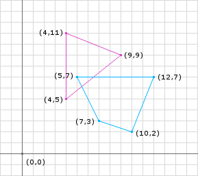
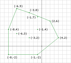
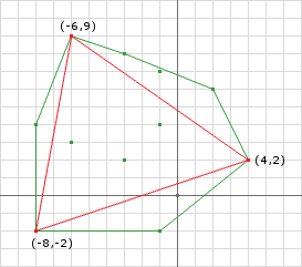
Lets look at an example, take the two shapes in figure 1 and perform the Minkowski Difference on them and you will get the shape in figure 2. Notice that the resulting shape contains the origin. This is because the shapes are intersecting.
Now performing this operation required shape1.vertices.size * shape2.vertices.size * 2 subtractions. This is significant because a shape is made up of an infinite number of points. Since both shapes are convex and defined by outermost vertices we only need to perform this operation on the vertices. The great thing about GJK is that you don’t actually have to calculate the Minkowski Difference.
The Simplex
We don’t want to compute the Minkowski Difference. Instead we just want to know whether the Minkowski Difference contains the origin or not. If it does, then we know that the shapes are intersecting, if it doesn’t, then they aren’t.
Instead what we can do is iteratively build a polygon inside the Minkowski Difference that attempts to enclose the origin. If the polygon we build contains the origin (and is contained in the Minkowski Difference) then we can say the Minkowski Difference contains the origin. This polygon that we want to build is called the Simplex.
The Support Function
So the next question is how do we build the Simplex? The Simplex is built using whats called a Support Function. The support function should return a point inside the Minkowski Difference given the two shapes. We already know that we can take a point from shape1 and a point from shape2 and subtract them to obtain a point in the Minkowski Difference, but we don’t want it to be the same point every time.
We can ensure that we don’t get the same point every call to the support function if we make the support function dependent on a direction. In other words, if we make the support function return the farthest point in some direction, we can choose a different direction later to obtain a different point.
Choosing the farthest point in a direction has significance because it creates a simplex who contains a maximum area therefore increasing the chance that the algorithm exits quickly. In addition, we can use the fact that all the points returned this way are on the edge of the Minkowski Difference and therefore if we cannot add a point past the origin along some direction we know that the Minkowski Difference does not contain the origin. This increases the chances of the algorithm exiting quickly in non-intersection cases. More on this later.
public Point support(Shape shape1, Shape shape2, Vector d) {
  // d is a vector direction (doesn't have to be normalized)
  // get points on the edge of the shapes in opposite directions
  Point p1 = shape1.getFarthestPointInDirection(d);
  Point p2 = shape2.getFarthestPointInDirection(d.negative());
  // perform the Minkowski Difference
  Point p3 = p1.subtract(p2);
  // p3 is now a point in Minkowski space on the edge of the Minkowski Difference
  return p3;
}
Creating The Simplex
Lets start with an example. Using the shapes in figure 2 and performing the support function 3 times:
First lets start by using d = (1, 0)
p1 = (9, 9);
p2 = (5, 7);
p3 = p1 - p2 = (4, 2);
Next lets use d = (-1, 0)
p1 = (4, 5);
p2 = (12, 7);
p3 = p1 - p2 = (-8, -2);
Notice that p1 could have been (4, 5) or (4, 11). Both will produce a point on the edge of the Minkowski Difference.
Next lets use d = (0, 1)
p1 = (4, 11);
p2 = (10, 2);
p3 = p1 - p2 = (-6, 9);
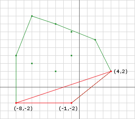
we obtain the Simplex illustrated in Figure 3.

Determining Collision
We said earlier that we know that the two shapes are intersecting if the simplex in the Minkowski Difference contains the origin. In Figure 3, the Simplex doesn’t contain the origin, but we know that the two shapes are intersecting. The problem here is that our first guess (at choosing directions) didn’t yield a Simplex that enclosed the origin.
If instead I choose d = (0, -1) for the third Minkowski Difference direction:
p1 = (4, 5);
p2 = (5, 7);
p3 = p1 - p2 = (-1, -2);
This yields the simplex shown in figure 4 and now we contain the origin and can determine that there is a collision.
the origin
So, as we have seen, the choice of direction can affect the outcome. We can also see that if we obtain a Simplex that does not contain the origin we can calculate another point and use it instead.
This is where the iterative part of the algorithm comes in. We cannot gaurentee that the first 3 points we choose are going to contain the origin nor can we guarentee that the Minkowski Difference contains the origin. We can modify how we choose the points by only choosing points in the direction of the origin. If we change the way we choose the third Minkowski Difference point to below we can enclose the origin.
d = ...
a = support(..., d)
d = ...
b = support(..., d)
AB = b - a
AO = ORIGIN - a
d = AB x AO x AB
c = support(..., d)
Because the d that c will be using is dependent on a and b forming a line, we can choose b such that it is as far away from a as possible by using the opposite direction:
d = ...
a = support(..., d)
b = support(..., -d)
AB = b - a
AO = ORIGIN - a
d = AB x AO x AB
c = support(..., d)
So now we only need to choose d for the first Minkowksi Difference point. There are a number of options here, an arbitrary direction, the direction created by the difference of the shapes centers, etc. Any will work but some are more optimal.
NOTE: AB stands for “point A to point B” which is found by taking B – A not A – B. This holds for the remainder of the post. AO, AC, etc. all follow this format.
Iteration
Even though we changed the above to determine collision we still may not get a Simplex that contains the origin in those three steps. We must iteratively create the Simplex such that the Simplex is getting closer to containing the origin. We also need to check for two conditions along the way: 1) does the current simplex contain the origin? and 2) are we able to enclose the origin?
Lets look at the skeleton of the iterative algorithm:
Vector d = // choose a search direction
// get the first Minkowski Difference point
Simplex.add(support(A, B, d));
// negate d for the next point
d.negate();
// start looping
while (true) {
  // add a new point to the simplex because we haven't terminated yet
  Simplex.add(support(A, B, d));
  // make sure that the last point we added actually passed the origin
  if (Simplex.getLast().dot(d) <= 0) {
    // if the point added last was not past the origin in the direction of d
    // then the Minkowski Sum cannot possibly contain the origin since
    // the last point added is on the edge of the Minkowski Difference
    return false;
  } else {
    // otherwise we need to determine if the origin is in
    // the current simplex
    if (Simplex.contains(ORIGIN)) {
      // if it does then we know there is a collision
      return true;
    } else {
      // otherwise we cannot be certain so find the edge who is
      // closest to the origin and use its normal (in the direction
      // of the origin) as the new d and continue the loop
      d = getDirection(Simplex);
    }
  }
}
Next lets use the skeleton with our example in Figure 1. Lets set our initial direction to the vector from the center of shape1 to the center of shape2:
d = c2 - c1 = (9, 5) - (5.5, 8.5) = (3.5, -3.5) = (1, -1);
p1 = support(A, B, d) = (9, 9) - (5, 7) = (4, 2);
Simplex.add(p1);
d.negate() = (-1, 1);
Then we start the loop:
Iteration 1
last = support(A, B, d) = (4, 11) - (10, 2) = (-6, 9);
proj = (-6, 9).dot(-1, 1) = 6 + 9 = 15
// we past the origin so check if we contain the origin
// we dont because we are line
// get the new direction by (AB x AO) x AB = B(A.dot(C)) - A(B.dot(C))
AB = (-6, 9) - (4, 2)  = (-10, 7);
AO = (0, 0) - (-6, 9) = (6, -9);
ABxAOxAB = AO(149) - AB(-123)
              = (894, -1341) - (1230, -861)
              = (-336, -480)
              = (-0.573, -0.819)
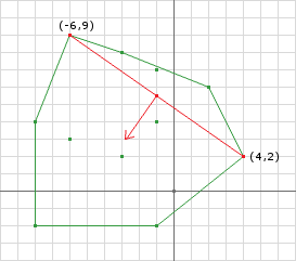
Figure 5 shows the resulting simplex after iteration 1. We have a line segment (brown) simplex with the next direction (blue) pointing perpendicular to the line towards the origin. One note, the direction does not need to be normalized (see iteration 2) but I’m doing it here so we can verify the direction given our scale.
Iteration 2
last = support(A, B, d) = (4, 5) - (12, 7) = (-8, -2)
proj = (-8, -2).dot(-336, -480) = 2688 + 960 = 3648
// we past the origin so check if we contain the origin
// we dont (see Figure 6a)
// the new direction will be the perp of (4, 2) and (-8, -2)
// and the point (-6, 9) can be removed
AB = (-8, -2) - (4, 2)  = (-12, -4);
AO = (0, 0) - (-8, -2) = (8, 2);
ABxAOxAB = AO(160) - AB(-104)
              = (1280, 320) - (1248, 416)
              = (32, -96)
              = (0.316, -0.948)
New Simplex
New Simplex And Direction
After the second iteration we have not enclosed the origin yet but still cannot conclude that the shapes are not intersecting. In the second iteration we removed the (-6, 9) point because all we need is 3 points at any time and we add a new point at the beginning of every iteration.
Iteration 3
last = support(A, B, d) = (4, 5) - (5, 7) = (-1, -2)
proj = (-1, -2).dot(32, -96) = -32 + 192 = 160
// we past the origin so check if we contain the origin
// we do (Figure 7)!
Collision Detected
Checking The Simplex
We have glazed over two operations in the algorithm, using just pictures and inspection. One is, how do we know that the current simplex contains the origin? The other being, how do we choose the next direction? In the pseudo code above I made these operations separate for the sake of clarity, but in reality they really should be together since they need to know much of the same information.
We can determine where the origin lies with respect to the simplex by performing a series of plane tests (line tests for 2D) where each test consists of simple dot products. The first case that must be handled is the line segment case. So lets look at the first iteration from the example above. After adding the second point on line 9, the simplex is now a line segment. We can determine if the simplex contains the origin by examining the Voronoi regions (see Figure 8).
The line segment is defined as A to B where A is the last point added to the simplex. We know that both A and B are on the edge of the Minkowski Difference and therefore the origin cannot lie in R1 or R4. We can make this assumption because the check from line 11 returned false indicating that we passed the origin when we obtained our next point. The origin can only lie in either R2 or R3 and since a line segment cannot contain the origin then all that needs to be done is to select a new direction. This can be done, as previously stated, by using the perp of AB in the direction of the origin:
// the perp of AB in the direction of O can be found by
AB = B - A;
AO = O - A;
perp = AB x AO x AB;
The catch here is what happens when O lies on the line? If that happens the perp will be a zero vector and will cause the check on line 11 to fail. This can happen in two places: 1) inside the Minkowski Sum and 2) on the edge of the Minkowski Sum. The latter case indicates a touching contact rather than penetration so you will need to make a decision on whether this is considered a collision or not. In either case, you can use either the left or right hand normal of AB as the new direction.
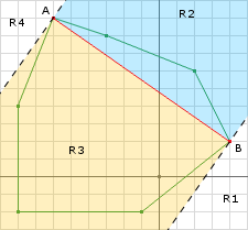
Now lets examine the second iteration. The second iteration turns our simplex into a triangle (Figure 9).
The white regions do not have to be tested since the origin cannot be past any of those points since each point was added because they passed the check on line 11. R2 cannot contain the origin because the last direction we choose was in the opposite direction. So the only regions to test are R3, R4, and R5. We can perform AC x AB x AB to yield the perpendicular vector to AB. Then we perform: ABPerp.dot(AO) to determine if the origin is in region R4.
AB = (-6, 9) - (-8, -2) = (2, 11)
AC = (4, 2) - (-8, -2) = (12, 4)
// AC x AB x AB = AB(AC.dot(AB)) - AC(AB.dot(AB))
ABPerp = AB(68) - AC(125)
          = (136, 748) - (1500, 500)
          = (-1364, 248)
          = (-11, 2)
// compute AO
AO = (0, 0) - (-8, -2) = (8, 2)
ABPerp.dot(AO) = -11 * 8 + 2 * 2 = -84
// its negative so the origin does not lie in R4
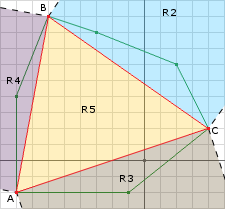
So with one more test we can determine where the origin lies:
AB = (-6, 9) - (-8, -2) = (2, 11)
AC = (4, 2) - (-8, -2) = (12, 4)
// AB x AC x AC = AC(AB.dot(AC)) - AB(AC.dot(AC))
ACPerp = AC(68) - AB(160)
           = (816, 272) - (320, 1760)
           = (496, -1488)
           = (1, -3)
// compute AO
AO = (0, 0) - (-8, -2) = (8, 2)
ACPerp.dot(AO) = 1 * 8 + -3 * 2 = 2
// its positive so that means the origin lies in R3
So we have found that the origin lies in R3 so now we need to select a direction so that we get our next Minkowski Difference point in that direction. This is easy since we know that AC was the line segment whose Voronoi region the origin was contained in:
AC x AO x AC
And since we are using points A and C we can get rid of B since we didn’t use it. The new code becomes:
Vector d = // choose a search direction
// get the first Minkowski Difference point
Simplex.add(support(A, B, d));
// negate d for the next point
d.negate();
// start looping
while (true) {
  // add a new point to the simplex because we haven't terminated yet
  Simplex.add(support(A, B, d));
  // make sure that the last point we added actually passed the origin
  if (Simplex.getLast().dot(d) <= 0) {
    // if the point added last was not past the origin in the direction of d
    // then the Minkowski Sum cannot possibly contain the origin since
    // the last point added is on the edge of the Minkowski Difference
    return false;
  } else {
    // otherwise we need to determine if the origin is in
    // the current simplex
    if (containsOrigin(Simplex, d) {
      // if it does then we know there is a collision
      return true;
    }
  }
}

public boolean containsOrigin(Simplex s, Vector d) {
  // get the last point added to the simplex
  a = Simplex.getLast();
  // compute AO (same thing as -A)
  ao = a.negate();
  if (Simplex.points.size() == 3) {
    // then its the triangle case
    // get b and c
    b = Simplex.getB();
    c = Simplex.getC();
    // compute the edges
    ab = b - a;
    ac = c - a;
    // compute the normals
    abPerp = tripleProduct(ac, ab, ab);
    acPerp = tripleProduct(ab, ac, ac);
    // is the origin in R4
    if (abPerp.dot(ao) > 0) {
      // remove point c
      Simplex.remove(c);
      // set the new direction to abPerp
      d.set(abPerp);
    } else {
      // is the origin in R3
      if (acPerp.dot(ao) > 0) {
        // remove point b
        Simplex.remove(b);
        // set the new direction to acPerp
        d.set(acPerp);
      } else{
        // otherwise we know its in R5 so we can return true
        return true;
      }
    }
  } else {
    // then its the line segment case
    b = Simplex.getB();
    // compute AB
    ab = b - a;
    // get the perp to AB in the direction of the origin
    abPerp = tripleProduct(ab, ao, ab);
    // set the direction to abPerp
    d.set(abPerp);
  }
  return false;
}
This completes the tutorial for the GJK collision detection algorithm. The original GJK algorithm computed a distance between the two convex shapes. I plan to cover this portion of the algorithm in another post since this post is already way too long. Also, as I said earlier, if you need collision information (normal and depth) you will need to modify the GJK algorithm or supplement it with another algorithm. EPA is one supplement algorithm which I plan to cover in another post. Until next time…
Why is shape1.vertices.size * shape2.vertices.size * 2 subtractions?
I feel shape1.vertices.size * shape2.vertices.size is enough.
Yeah, I can see how that’s a little confusing. You are correct that there are only shape1.vertices.size * shape2.vertices.size number of vector subtractions. Since I’m working in 2D here its 2 subtractions per vector subtraction:
William
a little error:
= (32, -96)
= (0.316, -0.948)
Good catch, I fixed it within the post.
Thanks,
William
hi, william
In 2D, we keep simplex a triangle, if we only keep simplex a tetrahedrold in 3D?
so I think how to remove a vertex from tetrahedrold,…
1.first judge orign if in the voronoi area of 4 vetices. if it is in these area, it’ll no collision, for simplex vertices are vertices of minkowski difference shape.
2. jude orgin if in the 4 face voronoi area, if in a face voronoi area, we will choose direction of voronoi and remove vertex opposite this face.
3. otherwise, orgin in internia of tetrahedrod, it’s collison state.
is my idea right? if you supplement a 3D simplex checking, it will be perfect.
2. jude orgin if in the 4 face voronoi area, if in a face voronoi area, we will choose direction of voronoi and remove vertex opposite this face, insert new vertex to simplex by new direction.
Yes, that right. 3D should keep a tetrahedron. The process is the same just a little more complex since you have another dimension to worry about. Once you have a triangle, you will want to take the direction of the face of the triangle towards the origin to obtain the 4th point. Then, like you said, find the Voronoi region the origin is in. If it’s inside the tetrahedron then we can return true to indicate a collision. If it’s outside the tetrahedron, then we need to obtain a new search direction. The new search direction will be the normal of the face in the direction of the origin. The termination condition can remain the same “If the new point we found using the support function is not past the origin, projected onto the search direction, then we know that the origin is not in the Minkowski Sum and therefore the shapes are not colliding.”
I have not implemented the 3D version of GJK. If you watched video I linked to at the beginning of the post, it should be pretty easy to formulate the tetrahedron case. Initially I wouldn’t worry about reducing the “if” statements down to the minimum until you have something working.
I know that the opensource project has a 3D implementation of GJK (I have a very hard time reading that source code however, probably because my C++ is so rusty, but might have better luck)
thanks for your reply, william
I am reading bullet code, but its code is unreadable, so I decide to implement it by your turtorial.
your tutorial is so wonderful, it’s the best GJK tutorial on the web.
thanks again
Thanks! It’s good to hear that someone is getting some use out of it.
I would suggest you try to implement it yourself first (like you are trying to do), but if you get stuck you can continue to ask me questions and/or reference my 2D implementation . It’s part of a larger project called , so if you see me use some other classes, just browse up to find their implementation within that same project.
You will be most interested in the detect method that returns a boolean, since its the simplest.
William
hi, william
Vector d = // choose a search direction
02 // get the first Minkowski Difference point
03 Simplex.add(support(A, B, d));
04 // negate d for the next point
05 d.negate();
for the first point in simplex, we should add
if (Simplex.getLast().dot(d) <= 0)
determination. I think
such as : two tetrahedron
tetra.AppendVertex(VECTOR3D(0, 10, 0));
tetra.AppendVertex(VECTOR3D(-10, 0, 10));
tetra.AppendVertex(VECTOR3D(10, 0, 10));
tetra.AppendVertex(VECTOR3D(0, 0, -10));
tetra1.AppendVertex(VECTOR3D(20, 5, 0));
tetra1.AppendVertex(VECTOR3D(12, 0, 5));
tetra1.AppendVertex(VECTOR3D(15, 0, 0));
tetra1.AppendVertex(VECTOR3D(13, 0, -5));
initial direction is mass center vector.
Yes, you can do the check that is performed within the while loop for the first point as a performance/robustness improvement. In my implementation I have this, however, for the purpose of this post I wanted to focus more on understanding the algorithm. That initial check can also be added to the 2D version as well.
The algorithm will still terminate, but maybe after a few more iterations (performance). In addition to this, it may also cause some zero vectors when using the vector triple product (robustness).
You can reference my in the project .
I’m a bit confused. If all I need is to detect if the collision is happening and NOT care about the distance between the two objects A and B, does it mean, with the Minkowski difference giving the boundary of the set(A-B), I only need to determine is the origin is located in side that boundary by doing some dot and cross product of vectors?
Thanks a lot.
Yes, that’s exactly right. If you are only looking for a boolean true/false then you only need to create a simplex within the Minkowski sum (difference in our case) as outlined in this post. If you can create a simplex that contains the origin, then the shapes are colliding, otherwise they are not.
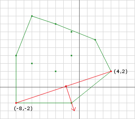
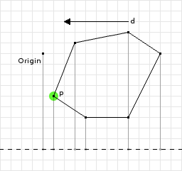
Here is the same example just the blue shape has been translated (1, -1). Notice how the Minkowski sum shape doesnt change, it only moves (-1, 1). If you run through the code above using this example you will notice that the condition:
// make sure that the last point we added actually passed the origin
if (Simplex.getLast().dot(d) <= 0) {
Will fail during the “create simplex” iteration. If at any point this condition fails then we know that they shapes are not overlapping.
We can start from any point in the Minkowski difference, but how do you choose the point added on later in the direction we’re searching? I mean how to numerically determine one point on the edge is the farthest in the direction we’re looking for? Should I just use all the vertices on the boundary?
I’m trying to do a 3D collision model. So if contact happens, doing the Minkowski difference of all the vertices on object A and object B will generate a polyhedron. So, can I divide this polyhedron into several tetrahedrons and check if the origin lies in one of them? This sounds like involving some more unnecessary calculation.
Thanks,
Good question. Yes you can start anywhere, although I would start with a point that was found the way all the others will be. This way you ensure that the point is on the edge of the Minkowski sum. You can find the point farthest in any direction by projecting all the points of the polygon onto the direction vector:
For instance if d was (1, 0):
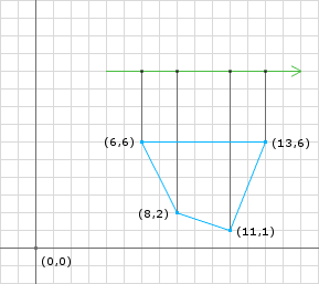
We can see that the point (13, 6) is the farthest point in that direction. We can mathematically obtain this result if we perform the dot product of the points with the direction:
Yes, if you need to show the Minkowski sum, then you must subtract all possible combinations of the points from both objects and take the convex hull of the resulting point set (notice in the picture above that some points are inside the Minkowski sum and are therefore ignored).
To determine whether there is collision between the two shapes you don’t have to subdivide the Minkowski sum. That’s what make this algorithm fast, in that you only have to iteratively build one tetrahedron inside the Minkowski sum that contains the origin. If you cannot, then the shapes are not colliding.
AB = a – b
AO = a – ORIGIN
Should that be AB = b – a
AO = ORIGIN – a
Thanks for pointing that out, I fixed it within the post. Oddly enough, I had it correct in the Checking The Simplex section…
William,
We feel you are contributing very well here. Would you be interested in authoring a book chapter, possibly a tutorial on GJK, for our upcoming book on Video Game Design? If interested, send me an email.
KEB
I was wondering about the triple cross products, ex: (AB x AO) x AB . I’m having to review my vector algebra, and trying to figure out how to point the perpendicular vector in the right direction. How did you come to select that particular order?
I’m one of those that has to understand how something works before I can use it.
That’s funny because I’m the exact same way. If I don’t understand it, I wont use it either. Using the cross product requires you to define the “handedness” of your coordinate system. A right handed system is typically chosen.
If we look at the image below the cross product of the two vectors a and b yield another vector that is perpendicular to both of these vectors. We have to define the handedness because there are actually two vectors that meet that criteria. One points out from the plane and the other points into the plane.
If we choose a right handed system, we literally line up our right hand index finger with the first vector, a, and then line up our middle finger with the second vector, b. Your thumb points in the direction of the result, in this case out from the plane.
So if we wanted to get the normal of an edge, we can take the cross product to get a vector perp to both vectors, then cross product one more time to get a vector perp to the result and the original edge.
Yeah, I suppose the trickiest thing for me is to figure out which direction the vector is heading on the third cross.
Maybe these images will help.
Imagine the vectors a and b in the xy-plane. The cross product of those vectors, in a right handed coordinate system, yields the vector a x b along the positive z-axis.
For the next image we imagine that the a x b vector is the new a vector. So we line up our right hand index finger along a x b and our middle finger along b and we get the final vector (a x b) x b which lies in the xy-plane.
Hi William.
First of all, thanks! Your tutorial is so far the best I’ve found on the Internet. I’ve just implemented a simple INTEGER version of the algorithm, according to your explanation. Some math aspects are still not so clear but I’m going to work on it. Thus, sorry in advance if I’m wrong with what I’m going to tell you. :)
I have to check my code carefully to find any bug. Anyhow, I have a question. I’ve tested different spatial configuration of two shapes and I’ve seen that the code has a strange behaviour.
In your tutorial you talk about cases in which the perpendicular line of a two vertexes simplex (AB) is 0 because of the origin laying on the AB line. I’ve noticed that, when one of the shape is simply translated w.r.t. the other, or else when the two shapes align on an axis, I have the same behaviour.
Is that a wrong behaviour or simply the effect of using integers? Using floating point that would really be a rare case. Indeed, two floating points are hardly the same. So it’s for floating coordinates.
Changing the check that relies on the direction (the one at your 11th line) from “<=" to "<", everything seems to work. Obviously contact cases are seen as collisions, but that's a behaviour I would have.
If the behaviour is ok, the second question is: should I use the normal of AB as new direction (as you suggest) or just use the (0,0) direction? Does this affect only velocity or also correctness of the algorithm?
Again, thanks for your answer and sorry if I misinterpreted something.
Cheers,
F.
Thanks, it’s always good to hear that it was of some use.
I haven’t implemented an integer version of the algorithm before, so I’ll try my best. Getting the zero vector as the new direction is a problem because the support method could return a point that’s not on the edge of the Minkowski Difference. This is because the getFarthestPointInDirection will always return the last vertex in the polygon for both polygons (because of the dot product). Getting a point that is not on the edge of the Minkowski Difference causes the if on line 11 to be invalid.
However, this is a case that is inherent in the algorithm, so its not necessarily a bug, we just need to handle the case by doing something else like using the normal. For the line segment case you can use the right hand perpendicular vector. Thankfully, the normals in the triangle case don’t suffer from the this problem unless the triangle is very small because they use the other edges in the cross products instead of AO.
I would suggest to always use the normal (or maybe even another arbitrary direction) instead of the zero vector. This will ensure that the support method always returns a valid point for the if on line 11.
William
Awesome tutorial! I have a question about the AB x AO x AB.
First of all, I’m not a huge mathematician, so I’m wondering how to find the cross product of two unit vectors.
But more importantly, I don’t understand how this helps. I understand that it will give us a vector on the xy plane that is perpendicular to AB, and I get that. But how does it get which direction it should point? I mean, won’t a vertical vector x AB always result in the same vector, no matter which way AO was pointing to create the vertical vector?
And even if it does do that somehow, would it not just be easier to get a perpendicular vector to AB, and then negate it if necessary? (AKA, if the projection of A (or B) on to the vector is greater than or less than the origin projected onto it.)
Well, I just implemented it using my way, and it works fantastically. So unless there is any reason (speed?) that your way is better, I’m going to stick with the way I understand more. Awesome tutorial again!
Great questions!
An easier way to calculate the triple product is using the .
The triple product obtains the vector perpendicular to the vector AB in the direction of the origin by the handedness of the coordinate system. Most coordinate systems use the right hand rule, which means to (literally) line your index finger up with the first vector, in this case AB, then line up your middle finger with AO, then whatever direction your thumb is pointing, that will be the direction of the result. Then you line up your index finger with the last result and line your middle finger up with AB, then the result is in the direction of your thumb. This is how the triple product obtains the correct direction. Take a look at the image for an example of what I mean. In our case we have to use the right hand rule twice because there are two cross products.
The result of vector x AB can return two different vectors depending on the direction of vector, in our 2D case, vector can be pointing out of the plane or into the plane.
As you point out, in 2D you could simply get either the left or right normal easily by switching the x and y values and negating one, then check if you have the right direction by projecting it onto AO and negating if necessary. This is because there are only two perpendicular vectors to choose from. However, for 3D you must use the triple product because there are an infinite number of vectors perpendicular to AB.
William
Oh wow! If I had taken the time to really think about it, I would have gotten that. I was thinking at the time that the cross product was commutative in the sense that 2 vectors would produce the same cross product no matter what. That’s neat that it works out like that.
hi william:
for this section of code, i’m not quite understand
if (Simplex.getLast().dot(d) <= 0) {
  // if the point added last was not past the origin
  // in the direction of d
  // then the Minkowski Sum cannot possibly
  // contain the origin since the last point
  // added is on the edge of the Minkowski Difference
  return false;
}
why this is the exit criteria?
Good question. In words this is the exit condition because:
The last point in the simplex is the last point that was added to the simplex. This point is the farthest point in the Minkowski Sum in the given direction. If the point is not past the origin along d then we know that we can never enclose the origin. We know that the point is past the origin along d by performing the dot product of the new point with the direction vector.
Visually, here is a failure case:
The direction was (-1, 0). All the points projected onto d gave point p = (1, -4) to be the farthest. Then we come to the exit criteria where the projection of the point is compared against the projection of the origin. As we can see the p projected onto d, (-1, 0) · (1, -4) = -1, is less than the origin (the origin projected onto anything is zero). This makes sense since we have found the point farthest in a direction and the origin is still past that point, and since the Minkowski Sum is convex we know we can never find another point past the origin in this direction. Therefore we can never enclose the origin and we can immediately exit because no collision was found.
Could you kindly tell me how the center of shape1 and shape2 calculated?
Actually, I’m really glad you asked this because the center for shape1 was wrong. I fixed it and thankfully the flow of the post remains unchanged.
Finding the center of a 2D polygon can be done a number of ways. In this post I just picked a point that looked like the center to make the math easier. Typically you would do this using some algorithm. In there are two algorithms used to calculate the center:
1. Average Method – Add all the x values of the vertices and divide by the number of them; likewise with the y values. See
2. Area Weighted Method – See
William
d = c2 – c1 = (9, 5) – (5.5, 8.5) = (3.5, -3.5) = (1, -1);
p1 = support(A, B, d) = (9, 9) – (5, 7) = (4, 2);
Simplex.add(p1);
d.negate() = (-1.5, 1);
When I’m looking at this code, why is d.negate() = -1.5, 1? Intuitively I would expect negate to simply flip the signs of the direction, not change the direct itself. Since d started as 1,-1, how does negate change it to -1.5, 1?
By the way, super useful explanation otherwise. Just some minor confusion here.
Thanks! I actually had to change center points of the shapes because they were wrong. Then I updated the calculation, but must have missed that. I fixed it within the post.
One more issue:
“last = support(A, B, d) = (4, 5) – (12, 7) = (-8, -2)
proj = (-8, -2).dot(-336, -480) = 2688 + 960 = 3648
// we past the origin so check if we contain the origin
// we dont (see Figure 6a)
// the new direction will be the perp of (4, 2) and (-8, -2)
// and the point (-6, 9) can be removed
AB = (-8, -2) – (4, 2) = (-12, -4);
AO = (0, 0) – (-8, -2) = (8, 2);
ABxAOxAB = AO(160) – AB(-104)
= (1280, 320) – (1248, 416)
= (32, -96)
= (0.316, -0.948)”
Look very carefully at your calculation for AB and AO. Since A is (-8,-2), and AB is defined to be B-A, then AB cannot be (-8,-2) – (4,2). That would be the definition of BA.
Personally when I was coding this, this hung me up for a while, until I realized that if you literally do AB = B-A, then in the case of the line simplex, you are actually finding out the vector in the opposite direction of the origin, so this got me an infinite loop since I was always looking the wrong direction. (I spent some time using the right hand rule until I realized what was going on)
In other words, you did the calculation correctly (A-B) in order to get the perpendicular pointing in the direction of the origin, but the label is wrong, should be BA, and therefore BA X AO X BA.
(the other triple products are done correctly in the triangle simplex, just this line simplex caused my direction to be looking in the opposite direction of the origin).
Still, cheers, you saved my butt overall. I had no idea what was going on, even after watching mollyrocket’s video twice.
I’m both glad that the post helped and sorry that it cause you some debugging grief. I added a note early in the post clearly stating the definition of AB. This is actually the accepted notation for a vector that goes from point A to point B. Mathematically however, the evaluation of that vector is done is opposite order using the difference operator.
I’m a bit confused about one thing. If the origin lies on the line AB, why is it a contact point? Or are you talking about the bounding line of the Minkowski sum? If the latter is the case, how is that handled? I.e you get a null direction and terminate although the point resides in the Minkowski sum.
Good question. My comment in the post about this problem was a bit misleading. There are two places where the origin can lie on the edge of the simplex which can cause problems:
The latter case indicates touching contact and my intention was to point out this implication. It’s up to the developer to decide whether to call this a collision.
The former case just causes problems altogether. The fix I described in the comment in the post should work for both cases. Just get the left or right normal of the simplex AB and use that as the next direction.
I also fixed the comment in the post to help others.
William
Hi William, thanks for your very quick reply. I’m trying to implement GJK in 3D and I get into all kinds of trouble in the case where the origin lies ‘on’ (i.e. on the line or inside the triangle in 3D) the simplex. What you suggest works in 2D but in 3D (in the case of the edge of the tetrahedron) you have to take the cross product ABxAOxAB, which gives a null vector. You then also have to consider that we don’t have infinite precision which introduces additional complications.
I tried to read ch.4 of “Collision Detection in Interactive 3D Environments” by Gino van den Bergen. From my understanding, he introduces two additional checks on each iteration. He first computes the new point using the support function and then he returns ‘false’ if either the new point belongs to the previous simplex or if the origin lies farther than the new point. The second additional check is to return ‘true’ whenever the direction vector becomes relatively small.
This may be beyond the scope of this excellent tutorial but I hope it helps those interested in implementing it in 3D.
Yeah, as you point out, what I describe will only work in 2D.
If the origin lies on the triangle simplex plane (yielding a zero triple product), you can use the normal of the triangle plane by using the three vertices of the simplex instead. Either normal of the plane will work in this case (only two to choose from). For the line segment case in 3D, I would probably just choose an arbitrary direction (that is perp. to the line) so I could get to the triangle simplex case. Once you have a tetrahedron, its much easier to make better decisions about the “special” cases.
The Minkowski Sum algorithms (GJK and EPA) are typically harder to get correct for this very reason. Many of these “special” cases happen more often then you’d think. In addition, the finite precision doesn’t help.
Thanks for sharing what you found!
William
Hello, William!
Firstly, thanks for the awesome tutorial! You make it alot more simpler than everyone else does!
I have GJK almost working, however I’ve encountered one problem I can’t find the source of. I’ve made a little program for testing it out, in the form of two equal sized squares (80×80) and use the central points to obtain the first direction to check. One square can be moved about in 4 directions and upon detecing a collision, has its speed lowered to a noticable level.
HOWEVER: in a small perimeter around the static box, the collision because detected as true, even if the box isn’t touching. At first I thought this may just be a graphical error, then I noticed the speed is perfectly fine in that perimeter when the box is either in the region diagonal to the static box, or perfectly in line with it. To me, it seems as though the collision detection is going off as if there are extruding lines on the corners of the box, like so:
I’m unsure on their length since I haven’t tested it that much, but it seems to be having that effect (I noticed it when I move the box in to this field and moved it parallel to the edge of the box, when the moving box suddenly jolted, as if it was free of the invisible grasp).
Any idea what’s causing this? I thought it might be me just getting some >’s mixed up with some >=’s or something, but if it is, I haven’t pinned down which one.
Dunno if you still watch this post but there’s no harm in asking, ha.
Thanks in advance!
It’s hard for me to tell exactly what the problem might be without examining some code. The “jolting” of the penetration normal maybe correct in some cases, however the algorithm should only detect the collision if they are indeed overlapping.
Just a quick question, you said one of your boxes is 80×80. You are using floating point (and not integers) for the computations right? I’m sure you are, but I have to make sure.
The “jolting” of the penetration normal will happen when the minimum penetration shifts from one edge of a rectangle to another. This typically happens around the vertices. Let’s say two rectangles are overlapping normally and we get the penetration normal to be (-1.0, 0.0) (see figure A). Then let’s say that one of the rectangles moves up in one iteration (see figure B).
The normal was (-1.0, 0.0) but is now (0.0, 1.0). This is because (-1.0, 0.0) is no longer the vector with the minimum penetration depth. This is a side effect of the way that collision detection as defined what the collision normal is: the vector of minimum penetration. In practice this shouldn’t be a big problem.
Although it sounds like you have a different problem. Perhaps you can give a bit more details or post (or email) some code?
William
Okay, thanks! I’ll e-mail you the code I’m using.
I’m trying to understand the GJK algorithm for collission detection in my 2D Android game. I’m stuck at the description of iteration 1.
proj = (-6, 9).dot(-1.5, 1) = 9 + 9 = 18
should that not be:
proj = (-6, 9).dot(10,-7) = -60 +63 = 3.
This because (10,-7) = AB
sorry, correction, I mean at iteration 1:
proj = (6, -9).dot(10,-7) = 60 +63 = 123.
This because AB=(10,-7) and AO=(6,-9)
Good question. For whatever reason I had (-1.5, 1) for d but it really should be (-1, 1); I fixed this in the post. Using d (the first line of Iteration 1), we get (-6, 9) as the next support point (we now have 2 support points in our simplex). Then we need to make sure that the last support point we just added is past the origin along d; that’s what proj is for (the second line of Iteration 1):
proj = last.dot(d) = (-6, 9).dot(-1, 1) = -6 * -1 + 9 * 1 = 15
Since the dot product is greater than zero, then we know that the point is past the origin along d and we can continue the algorithm. Then next step is to find the next search direction (since we need 3 points to form a triangle to enclose the origin in 2D). To do this, we use the line segment case below in the section. Once we have a new search direction, we use it to obtain a new support point (just like we did with the original direction).
Let me know if something is still confusing here,
William
Thanks for your answer. I thought that I had to take AO.dot(AB),
because I watched the molleyrocket video and that’s the way they explained it.
If AO.dot(AB) > 0 it proves you passed the origin on your way from B to A.
You take last.dot(d) for the reason you explained.
But both tests will always give the same result (I think..)
hi William,
i think there should be a little improvement(through i am not very sure)
as you said “Instead what we can do is iteratively build a polygon inside the Minkowski Difference that attempts to enclose the origin.”,
so we need a line(triangle for 3D) before the ‘while’ looping(line 7 in your skeleton code), not a single point, then we never need to check whether the ‘Simplex’ has been built, or there is only a line in it.
Vector d = // choose a search direction

// get the first Minkowski Difference point

Simplex.add(support(A, B, d));

// negate d for the next point

d.negate();

Simplex.add(support(A, B, d));    //*** build the first line ****//

// start looping

while (true) {

  // same as your code

}
and Sorry, English is not my native language.
Yes. You can create a line segment and make sure its past the origin before beginning the while loop for a slight performance improvement.
The goal of this post was to introduce the topic and explain the algorithm. I tend to leave small improvements like this out because they tend to lose the reader. Once the reader understands the algorithm, these types of improvements are usually obvious.
William
Hi William,
Excelent post! Could you help me with this question?
I don’t understand how do you get (-0.573, -0.819) from (-336, -480), or how do you get (0.316, -0.948) from (32, -96) in one step. I understand that both pairs have the same reason (x/y), but, how do you exactly calculate those points? And, how do I interpret these points ((-0.573, -0.819) or (0.316, -0.948))? Because I see that you use (-336, -480) or (32, -96) in next iterations.
Thanks, and sorry but my english isn’t very good.
I am normalizing the vectors. You can normalize a vector by doing the following:
This process turns an arbitrary length vector into a vector of length 1.
The GJK algorithm as described here doesn’t require normalization however (the GJK distance algorithm does). But it was done in the computations to aid the reader in plotting/visualizing the computed vectors.
William
How can i choose the direction (Vector d) to get the farthest point in A, i know the direction of the farthest point of B will be d.neg().
Please i need help with this.
Once you are in the while loop the algorithm will choose the next direction in the containsOrigin method: d.set(…). So the only direction you need to choose is the first. This one can be chosen arbitrarily, but you would want to choose a direction which would allow the algorithm to exit early. For example, using the vector from the center of shape1 to the center of shape2 is a good option. This is what I used in the post (Iteration section, before iteration 1).
William
I’m so inspired by your tutorial, by the way, how can you make the images here? I mean, what program do you use?
I’m sorry for my quetions being so basic… I’m a greenhand in collision detection. I also want to know how can I image the minkowski difference like you did in this post.
I really really appreciate it, from your post I know where to start.
I use to do most of my figures. It’s a long and tedious process, but I’ve improved the quality and speed over time.
The brute force way to generate the Minkowski Sum is to take all the vertices in the first polygon and add them to all the vertices in the second polygon (subtract, rather than add, if you want the Minkowski Difference) which results in a point cloud. Next perform a on the point cloud to get the resulting shape:
Polygon p1 = // 1st polygon
Polygon p2 = // 2nd polygon

for each vertex in p1
  for each vertex in p2
    add p1 + p2 to the point cloud (a list, array, whatever)
  end for
end for

// finally perform a Convex Hull algorithm
// to get the Minkowski Sum's shape
Polygon result = convexHull(point cloud);
William
Thx a lot !
But I still cannot make it clear how to handle circles in 2D environment and balls in 3D environment, would you please give me some points? : )
To be specific, how to find a farthest point in a circle, how to identify a certain point in a circle.
and curves.
You can see my implementation of various shapes in dyn4j (look at each shape’s “getFarthestPoint” method).
You can also look at those same shapes to see the implementation of a “contains” method. Just ignore any stuff with Transform if its confusing.
Each shape type has its own implementation (or inherits the implementation of its super class) of the farthest point.
William
Gorgeous tutorial!
I am a newcomer in this area and I really want to know where to start.
I mean if I want to build a platform to perform all the algorithms and do some collision detection experiment , where should I start?
If convenient, can you give me your email or skype or msn?
I’m so sorry to waste your time but I really need a teacher like you to give me some guide.
Thanks a lot! : )
My email is
I want to know which book or material to read , and which language is necessary, though I don’t get any of these languages like c++, java, but I can get through the pseudo code you post here(several year ago I’ve learned a little about Visual Basic).
I don’t want to learn all of them in a fast way, I want to learn the way of thought about this area, and slowly build the platform on my own, like you did here.
: )
I’m sure these algorithms can be implemented in any language you choose. Just use whatever you are comfortable with. If you are not comfortable with any, I’d try to learn a programming language first.
That said, if you are looking for books or other material on this subject you should be able to find a lot more via google.
You can contact me directly at .
hello, great tutorial! i just wanted to say(ask) that in the video tutorial you suggest there are two extra IF checks in the triangle case (!?)
To make sure there is no confusion on attribution, the video was not mine, but rather the best explanation I had found (Kudos to Casey Muratori for putting it together).
The triangle case should only have up to 3 ifs, which is two more than the segment case, is this what you are referring to? If you give me the position in the video (in time) I might be able to answer better.
William
it starts at ~ 32:27 the IF AC case and similarly the IF check marked as a star
If I want to handle concave cases, would you please give me some advice, thx!
@ng:
I think later in the video he explains that the number of ifs for the triangle case can actually be reduced (I could be mistaken here). The number of ifs at this stage in the video is around 5-6 depending on how you count it.
If you think about the AC if and its else condition, you can see that its unnecessary. We obtain the A and C simplex points by getting the point farthest in the Minkowski Difference along a direction. We have a check on the loop that says we stop and return no intersection if any simplex point we find is not past the origin along that direction. Because of this check on the loop, we have already determined that the origin cannot lie in regions 5 and (i think, its hard to read) 6. If the origin was in either of those regions, then A and C would not have been valid simplex points and we would have exited the algorithm with no intersection already.
I talk about this in more detail in the Checking The Simplex section. You can also find more talk about the video on . The thread covers a number of improvements which were incorporated into my post here.
If you have more questions don’t hesitate to ask,
William
@Dimension:
There are two ways to handle concave shapes: 1) develop/find an algorithm that supports concave shapes or 2) decompose the concave shape into convex shapes.
My research into concave shape collision detection algorithms is minimal. Typically they are avoided due to complexity and run-time cost, but this may changed since I last looked.
Most go the second route and decompose the concave shape into convex shapes and perform collision detection using a convex algorithm. There are a number of methods to decompose concave shapes. I have listed a few that I have implemented in this comment on the SAT post. If you are working in 3D then you may be interested in . The convex decomposition can be done as a pre-processing step to save some time.
William
Thx a lot!! ^_^
Dear William, I want to try to apply the GJK in 3d dynamic environment, can you give me some advice? Thanks!
In 2D you only have two cases: the segment and triangle cases. For 3D you need one more case in addition to these: the tetrahedron case. By the time you have built a triangle simplex and verified that the origin is “inside” you need to add another simplex point in the direction of the origin. This is because the origin could be above or below the plane of the triangle. In other words, in 3D we may not have fully enclosed the origin yet. The algorithm proceeds as normal from here, do plane tests until you verify the origin is (or is not) contained in the tetrahedron. You can use the same logic as described in Casey’s video and my post here to try to reduce the number of “if” conditions for the tetrahedron case to make the code simpler.
If you give it a try and have more specific questions I’d be happy to answer,
William
Hello William,
I watched the video tutorial and read through. In the video, the third line of initialization should negate D (it reads D = -S in the video but his explanation is correct). I’m implementing a 2D version of GJK and have a question.
I think that the cross product direction update can be made faster by just rotating the vector AB in the direction of the origin. What do you think?
I’m not sure, I think it depends on the implementation of the trigonometric functions.
My implementation of the triple product has 8 multiplies, 2 adds, and 2 subtractions for a total of 12 operations. If the trigonometric functions are implemented using CORDIC or Taylor series, I think the triple product will win out. If I’m not missing anything, you would need 3 trigonometric function calls to perform the rotation: 1 (arctan2 probably) to obtain the angle of rotation and 2 (sin/cos) to perform the rotation?
William
No trig function calls required, rotation sare 90 degrees, you just flip the coords and negate one of them.
How will know which direction to rotate (90 or -90)? Can you give the full details on what you intend to replace?
I’m answering under the assumption you are trying to replace the triple products (you said cross product, can you clarify this?) inside the triangle simplex case with a rotation of the edge. Given that assumption, I think you would need to know the winding of the simplex to know which direction to rotate (the winding can change each iteration).
William
I’ll do the 2-simplex case with pseudo-code. Assume there is a macro or function that tells you whether a vector is to the left with respect to another (vector A is to the left of B if you have to rotate left starting at B to get to A). We can use determinant to answer this quickly (det(A B) > 0 means A is to the left of B assuming y-axis points downwards). Assume that direction vector is called D.
2-simplex case: simplex = [A, B, C] so C is the latest point
if CA is to the left of CO (det(CA CO) > 0):
if CA and CO point to the same direction (dot > 0):
D = rotateRight(CA) // D.x = -CA.y; D.y = CA.x (depends on coords-system)
simplex = [A, C]
else
D = CO
simplex = [C]
else if CB is to the right of CO (= CO is to the left of CB):
if CB and CO point to the same direction:
D = rotateLeft(CB) // D.x = CA.y; D.y = -CA.x
simplex = [B, C]
else
D = CO
simplex = [C]
else
return true // Simplex contains origin
————-
There are no triple products involved here, coord and sign flips do the job and there is no need for a function to test if a point is inside a 2-simplex so it’s faster (maybe). I hope this is clearer.
Spaces were trimmed from last post so I’ll re-post with points to mark indentation:
if CA is to the left of CO (det(CA CO) > 0):
..if CA and CO point to the same direction (dot > 0):
….D = rotateRight(CA) // D.x = -CA.y; D.y = CA.x (depends on coords-system)
….simplex = [A, C]
..else
….D = CO
….simplex = [C]
else if CB is to the right of CO (= CO is to the left of CB):
..if CB and CO point to the same direction:
….D = rotateLeft(CB) // D.x = CA.y; D.y = -CA.x
….simplex = [B, C]
..else
….D = CO
….simplex = [C]
else
..return true // Simplex contains origin
Dear William:
In 3D , is the following simple process right?
(1) first we check whether the point we got through a certain direction pass the origin, which equals to check if the point is in the point VR of the MK Difference;
if it doesn’t then return false, meaning collision doesn’t exist.
if it does then we add it to the simplex;
* redo the above until the simplex have 4 points, making up a tetrahedron.
(2)then we go to check if the origin lies in the 4 face VR by using the perps and dot product;
if it lies in one of them, then we use the perp of that face as our new searching direction and get rid of the present useless point of the simplex and rebuild the simplex and do the same thing from * .
if it doesn’t then the origin is surely inside the simplex and we get the collision detected.
end
@Futurecoming
That’s correct. Just be a little more accurate, as each point is added to the simplex we check where the origin is so that we build up to the tetrahedron case in the direction of the origin. In otherwords, we are trying to enclose the origin at every step, not just after we have a tetrahedron. Ideally we would get the 4th point to make the tetrahedron and immediately detect the origin inside. Technically you could build the tetrahedron however you want, but if we continuously check where the origin is, relative to the simplex, then we can eliminate a lot of ifs in the triangle and tetrahedron cases like I described in the Checking The Simplex section.
William
@Saad
Thank you, that is much clearer. I’m assuming CO is the vector from C to the Origin. Given that is the case, the problem I see with the pseudo code is what if the origin is inside the simplex already? At first glance it’s not a problem because it would be to the right, but what if the winding of the simplex is clockwise (look at Figure 9 for an illustration and replace B and C)? The first if will be true, the next if will be true, and you will remove B and continue the algorithm, when you should have exited, reporting a collision.
The winding of the simplex is not constant either, it can change each iteration (since we always just append a new simplex point and we could have removed B earlier). That said, you could always compute the winding each iteration, then include that in the logic.
Have you developed the Vector.isLeftOf(Vector) function? Without thinking it through, I have another function that finds which side a point is relative to a line which has 7 operations. To find the winding you will need to do one cross product which will be 3 operations. So you may come out on top. I’d be interested to know, how many operations you have once it’s all working.
William
I have a first version of GJK written in C. It needs testing though. If you have tested your code and still have the test cases, I’d be interested in using them to test mine. I’m pretty sure that you can find the orientation of a vector with respect to another by just taking the determinant (some authors use the term cross product to refer to that quantity but that’s an abuse as cross products are defined for 3-vectors only). You can take a look at the algorithms textbook (commonly known as CLRS); the section on computational geometry uses this computation.
Here is a function that tells you whether the first vector (u) is to the left of the second vector (v):
bool isLeft(vector u, vector v)

{

  float cross = u.x*v.y - u.y*v.x;

  return cross < 0.0;

}
Example 1:
u = (2, 1) and v = (2, 0). u is obviously to the left of v. The cross gives -2 which is less than 0 so this test passes.
Example 2:
u = (2, 3) and v = (-5, -1). here u is to the right of v. The cross gives 13 which is not less than 0 so this test passes as well.
An extreme case is when the u and v are collinear (cross = 0). In that cases you can answer either left or right.
You can test if a point is on one side of a line by taking u to be that point and v to be any vector on the line.
Let me know,
saad
@Saad
My implementation of GJK is in Java and I use JUnit tests to do automated/regression testing. You can find the GJK test cases in the ShapeXShapeYTest files , although I’m not sure how useful they’ll be to you.
I found the best way to test was to setup a program in which, using the mouse, you can move around and/or rotate (at least) one of the shapes, while you continuously check for collision using your GJK implementation. You can also draw the collision normal when a collision is found to verify it’s pointing in the correct direction. Then just play with one shape putting in all sorts of configurations until you are confident it works (try all the pathological cases). From there you can just add test cases as you find bugs.
I think you will still need to know the winding of the simplex as well. For a simplex that has clockwise winding you need the verify if the vector is to the left, whereas for a simplex that has counter-clockwise winding you need to verify if the vector is to the right. You should be able to use one cross product to determine the winding. Remember that the winding may change each iteration of the algorithm.
William
Hello William,
This is a wonderful tutorial, thank you very much!
About the function getFarthestPointInDirection(), this seems to require O(n) time for a convex hull composed of n polygons. Are you aware of any algorithms that could speed up this process? Perhaps by partitioning the vertices in some “directional” boundaries? I am just wondering what is the best approach for searching for this farthest point?
Thanks again!
Francois
I think you meant O(n) where n is the number vertices in the shape. Typically, your number of vertices should be fairly low, but if you do have high vertex count polygons you have a couple of options. Here are a few I can think of:
William
Dear William
Here is the pseudo code I wrote, would you please help me to check it?
public Point support (Shape shape1, Shape shape2, Vector d) { Point p1 = shape1.getFathestPointInDirection(d); Point p2 = shape2.getFartestPointInDirection(d.negative()); Point p3 = p1.subtract(p2); return p3; } Vector d = Simplex.add(support(A, B, d ));; d.negate(); while (true) { Simplex.add(support(A, B, d)); if (Simplex.getLast().dot(d) 0) { Simplex.remove(b); d.set(ABCPerp); } else if(ABDPerp.dot(AO) < 0) { Simplex.remove(C); d.set(ABDPerp); } else if(ADCPerp.dot(AO) < 0) { Simplex.remove(b); d.set(ADCPerp); } else if(BCDPerp.dot(BO) < 0) { Simplex.remove(A); d.set(ADCPerp); } ABPerp = TripleProduct(ac, ab, ab); ACPerp = TripleProduct(ab, ac, ac); ADPerp = TripleProduct(ab, ad, ad); BCPerp = TripleProduct(bd, bc, bc); BDPerp = TripleProduct(bc, bd, bd); CDPerp = TripleProduct(-bc, cd, cd); else if(ABPerp.dot(AO) < 0 ) { Simplex.remove(C); Simplex.remove(D); d.set(ADCPerp); } else if(ACPerp.dot(AO) < 0 ) { Simplex.remove(B); Simplex.remove(D); d.set(ABPerp); } else if(ADPerp.dot(AO) < 0 ) { Simplex.remove(B); Simplex.remove(C); d.set(ADPerp); } else if(BCPerp.dot(BO) < 0 ) { Simplex.remove(A); Simplex.remove(D); d.set(BCPerp); } else if(BDPerp.dot(BO) < 0 ) { Simplex.remove(A); Simplex.remove(X); d.set(BDPerp); } else if(CDPerp.dot(CO) < 0 ) { Simplex.remove(A); Simplex.remove(B); d.set(CDPerp); } else { return true; } } else if(Simplex.points.size() == 2){ b = Simplex.getB(); ab = b - a; ABPerp = TripleProduct(ab, ao, ab); d.set(ABPerp); Simplex.add(support(A, B, d)); c = simplex.getC(); ac = c - a; ABCPerp = CrossProduct(ab,ac); d.set(ABCPerp); } else if (Simplex.points.size() == 3) { c = simplex.getC(); ac = c - a; ABCPerp = CrossProduct(ab,ac); d.set(ABCPerp); }just ignore the Chinese…
Are there convex polygons for which the support mapping can be computed really fast (convex shapes close to a circle)
@Saad
Are you asking if there are any fast methods of computing the support mapping for high vertex count polygons? If so, there are a few ways I can think of:
One option is to implement a cache for the direction and its resulting farthest point (for each shape, or for the support map as a whole). I believe the (CPU) library does this.
Another option would be to use the convexity of the shapes to our advantage again. We know, because the shape is convex, that if we test the first vertex (what determines the first vertex is arbitrary) in the shape and then test its neighbors, we can find the right direction to iterate to find the farthest vertex. This can eliminate half of the vertices from being tested. Another thing we can do is, once we are looping in the correct direction, i.e. the projections are increasing, we can stop and return on the next vertex whose projection is less than our current max. For example, take the blue shape in figure 1. If my direction is (0,-1) and I choose (7,3) as the first vertex I test, the (5,7) vertex will have a smaller projection than the (10,2) vertex (and (10,2) being bigger than the first). So, I would iterate over the vertices in the direction of (10,2). I then test (10,2) and find that it is now the farthest point and move to the next vertex. I then test (12,7) and find that its projection is less than my current farthest point’s projection, so I can stop and return (10,2). Obviously, this isn’t really helpful for low vertex count shapes, but you could always have an “if” that switches to this logic when the shape has more than X number of vertices.
William